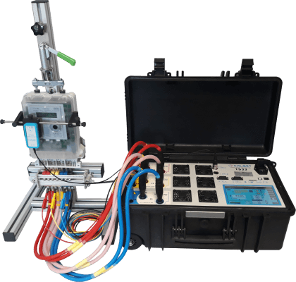
The Design
The Portable Meter Test System is designed to carry out meter testing at the site and in the laboratory as specified in the IEC and IS. It consists of
Application
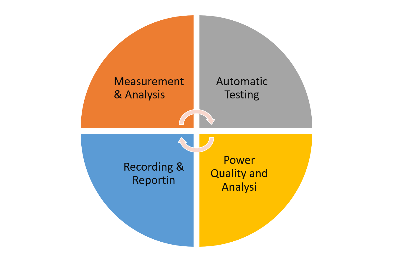
Functions and Features
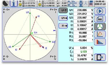
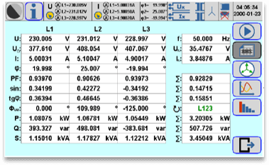
TS33- as a Reference Meter- Power Network and Power Quality Meter
TS33- as a three-phase source
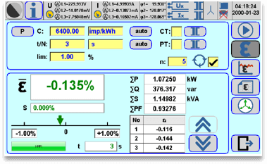
The TS33 power calibrator can work in two modes:TS33 as an Automatic Meter Tester
in this case, the TS33 is used as a test system with reference meter and integrated voltage and current source in manual or automatic operation mode with predefined (voltage and current) load points. with using following functionsTesting of Instrument Transformer
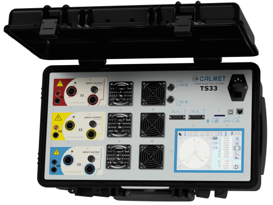
Three-phase Fully Automatic Portable Meter Test system
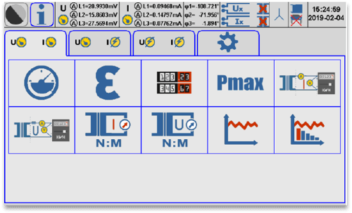
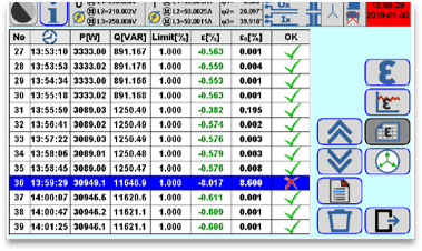
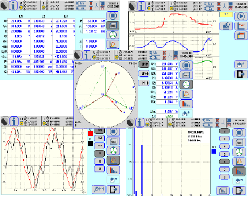
TS33 Main Display
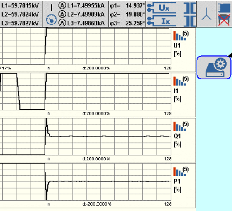
Power Quality Recording
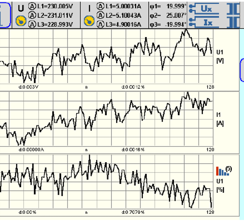
Parameter Recording
Technical Specification
|
Specification for the Output sinusoidal signals |
|||||
|
Parameter |
Range |
Settings span |
Resolution |
Accuracy 1)2) |
Maximum load |
|
Voltage U |
150V |
20...150V |
0.001V |
0.1% 4 |
200mA@150V |
|
300V |
150...300V |
0.01V |
100mA@300V |
||
|
600V |
300...600V |
0.01V |
SOmA@600V |
||
|
Voltage short term [10min] stability |
±0.01% |
|
|||
|
Voltage short term [1h] stability |
±0.03% |
|
|||
|
Voltage distortion factor |
< 0.5% |
|
|||
|
Current I |
0.12A |
0.02...0.12A |
0.00001A |
±0.1%3) ±0.1%*3) |
3V@0.12A |
|
1A |
0.12A...1A |
0.00001A |
±0.1%3) |
12V@1A |
|
|
12A |
1...12A |
0.0001A |
5.0V@12A |
||
|
120A |
12...120A |
0.001A |
0.65V@60A 0.5V@I20A |
||
|
Current short term [10min] stability |
±0.01% |
|
|||
|
Current short term [1h] stability |
±0.03% |
|
|||
|
Current distortion factor |
< 0.5%5) |
|
|||
|
Frequency f |
|
45...65Hz |
0.001Hz |
±0.02Hz4) |
|
|
Phase shift 0) |
|
-180...+180° |
0.001° |
±0.10°4) |
|
|
Phase shift short to m [10min] stability |
±0.05°4) |
|
|||
|
|||||
|
Specification for the Power Network Parameters |
||||||||
| Parameter | Range | Accuracy 1)2)3)4) | ||||||
| class 0.04 | class 0.1 | |||||||
| Voltage (Direct) | 0.05...600V | ±0.04% 5 | ±0.1%5 | |||||
| Voltage (VoltLiteWire 40kV) | 0.1...40kV | ±0.1%±Em | ||||||
| Current (Direct) | 0.01...120A 0.001...0.01A | ±0.04% ±0.04%* |
±0.1% ±0.1%• |
|||||
| Current (Clamps CT1OAC) | 0.1...12A 0.003...0.1A | ±0.2% ±0.2%• |
||||||
| Current (Clamps CT100AC) | 0.1...120A 0.01...0.1A ±0.2% | ±0.2%* | ||||||
| Current (Clamps CT1000AC) | 10...1200A 0.3...10A | ±0.2% ±0.2%* |
||||||
| Current (Flexible Clamps FCT3000AC) | 0.3...30A/3...300A/30...3000A | ±0.1%±Em | ||||||
| Current (AmpLiteWire 2000A) | 1...2000A | ±0.1%±Em | ||||||
| Power and energy (Direct) | 0.01...120A / 10...600V 0.001...0.01A / 10...600V | ±0.04% ±0.04%* |
±0.1% ±0.1%* |
|||||
| Power and energy (Clamps CT1OAC) | 0.1...12A / 10...600V 0.01...0.1A / 10...600V ±0.2% | ±0.2%* | ||||||
| Power and energy (Clamps CT100AC) | 0.1...120A / 10...600V 0.01...0.1A / 10...600V | ±0.2% ±0.2%* |
||||||
| Power and energy (Clamps CT1000AC) | 10...1200A / 10...600V 1...10A / 10...600V ±0.2% | ±0.2%* | ||||||
| Power and energy (Flexible Clamps FCT3000AC.B) | 0.3...30A/3...300A/30...3000A / 10...600V | ±0.1%±Em | ||||||
| Power and energy (VoltLiteWire 40kV + AmpLiteWire 2000A) | 1...2000A / 0.5...40kV | ±0.1%±Em | ||||||
| Frequency | 40...70Hz | ±0.01Hz | ||||||
| Phase shift (Direct) | -180...+180° | ±0.02°5)6) | ±0.04° 5)6) | |||||
| Phase shift (Clamps) | -180...+180° | ±0.1° 5)7) | ||||||
| Power factor cosy and sine | 0...±1 | ±0.001 5)6)7) | ||||||
| Temperature coefficient (Direct) | 0.001% per 1°C in range -10...+50°C | |||||||
| Time stability (Direct) | Short term f1h] = 0.01%, long term 11 year] = 0.03% | |||||||
| Power short term f1h] stability (Direct) | ±0.010% | ±0.020% | ||||||
| Power long term 11 year] stability (Direct) | ±0.025% | ±0.050% | ||||||
| Power temperature coefficient per 1°C (Direct) | ±0.002% | ±0.005% | ||||||
|
||||||||
| Specifications for the power quality parameters | ||||||||
| Parameter | Range | Accuracy 1) | ||||||
| Harmonics in voltages, currents, P and Q powers | amplitude | 0...100% of input | 1st....63rd | ±0.1% 2) | ||||
| phase | -180...+180° | ±0.5° 3) | ||||||
| Total harmonic distortion THD in voltages and currents | 0...100% of Input | 1st....63rd | ±0.1% 2) | |||||
| Total interharmonic distortion TID in voltages and currents | 0...15% of input | 40...3200Hz | ±0.2% 4) | |||||
| Signal voltage 5) | 0...15% of input | 40...3200Hz | ±5% | |||||
| Voltage asymmetry | 0...100% | ±2% | ||||||
|
||||||||
| Specifications for Burden measurement of PT and CT Transformers | |||
| Parameter | Current range | Voltage range | Accuracy 1)2) |
| CT Burden | 0.01...12A (Direct) | 1...10V (Direct) | ±0.2% |
| 0.05...1V (Direct) | ±0.2%* | ||
| Cr Burden | 0.1...120A (Clamps CT100AC) | 1...10V (Direct) | ±0.4% |
| 0.05...1V (Direct) | ±0.4%* | ||
| PT Burden | 0.01...12A (Direct) | 10...600V (Direct) | ±0.1% |
| 0.001.. 0 01A (Direct) | 30.1%* | ||
| 0.1...12A (Clamps CT100AC) | ±0.2% | ||
| Parameter | Primary current/voltage range | Secondary current/voltage range 0.1...120A (Clamps CT100AC) | Accuracy 1)2)3) ±0.4% |
| CT Ratio | 0.2...120A (Clamps CT100AC) | ||
| 0.01...12A (Direct) | ±0.2% | ||
| 0.001...0.01A (Direct) | ±0.2%* | ||
| CT Ratio | 10...1200A (Clamps CT1000AC) | 0.1...120A (Clamps CT100AC) .01...12A (Direct) | ±0.4% |
| CT Ratio | 0.3...30A/3...300A/30...3000A (Flexible Clamps FCT3000AC.B) 1...2000A (AmpLiteWire 2000A) | ±0.1%±Em | |
| CT Ratio | ±0.1%±Em | ||
| PT Ratio | 0.5...40kV (VoitLIteWire 40kV) | 10...600V (Direct) | ±0.1%±Em |
|
|||